I finally received the parts that I had ordered, some was on back order and slow delivery. Some plans have also changed, Brum wont have bluetooth communication right now and instead use a 16×2 LCD display for relaying what is going on in the program. Might use the bluetooth in the future.

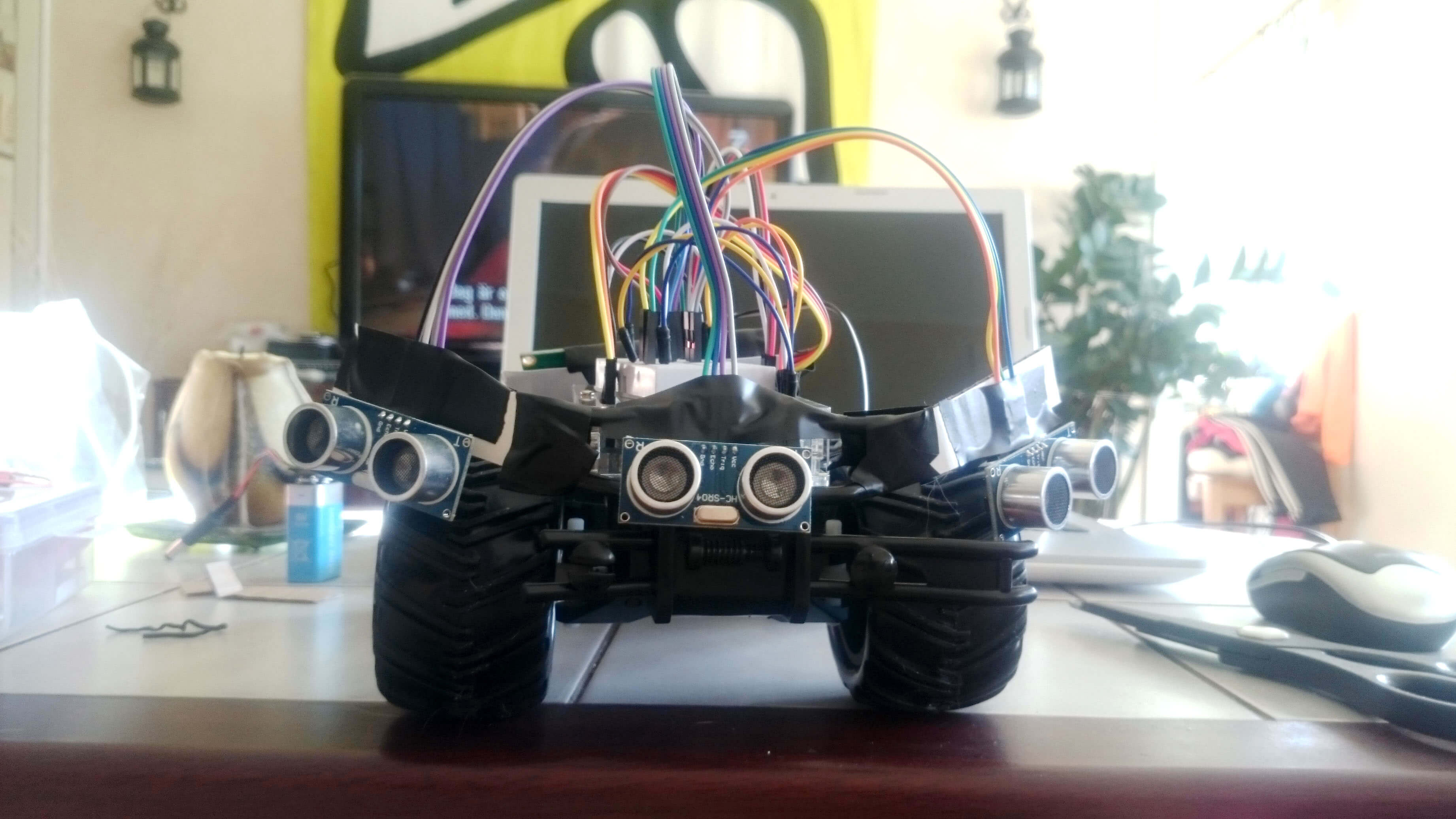
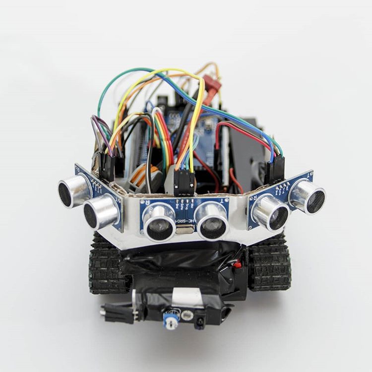
I did an initial component layout test to get a visualisation of where everything was going to be placed, see what brackets will need to be constructed etc. (See pic 1)
The next step was to hook up the motor drive board and test run the engines to see if and how it works. For this I put together a small test code from code I found when googleing (can’t find the source now but let me know if it’s your code and I will update with links and credit!). The chip on the driver board is HG7881 turned out to be not that common so propper info was some what hard to find. The most important thing to remember is to run it of an external power source and when switching direction on the engines the speed value(goes from 0 – 255) is reversed! (So 0 = 255 and 255 = 0). The code below is without the LCD but files with and without the LCD code can be found at the end.
A demo-video of the code running can be found after the code.
The Code
/**
 * Engine test code for HG7881
 * Author: Henrik Norberg
 * E-mail: henrik@dbhn.se
 */

/**
 * Create variables to be used to run motor A
 */
int motorAPin_A = 8; //Arduino digital 8 is connected to HG7881's A-1A terminal
int motorAPin_B = 9; //Arduino digital 9 is connected to HG7881's A-1B terminal

int motorBPin_A = 10; //Arduino digital 8 is connected to HG7881's B-1A terminal
int motorBPin_B = 11; //Arduino digital 9 is connected to HG7881's B-1B terminal

void setup(){
  /**
   * When program starts set Arduino pinmode for 8 and 9 digital to be OUTPUT
   * so we can use analogWrite to output values from 0 to 255 (0-5V) (PWM)
   */
  pinMode(motorAPin_A, OUTPUT); //direction
  pinMode(motorAPin_B, OUTPUT); //speed

  pinMode(motorBPin_A, OUTPUT); //direction
  pinMode(motorBPin_B, OUTPUT); //speed
}

void loop() {
  //set motor direction to "X"
  analogWrite(motorAPin_A, LOW);

  //start motor and increase speed while spinnning to direction "X"
  for(int i=0; i<=255; i++){
    //motor speed increases while we loop trough
    //values from 0 to 255 (0V to power supply max voltage)
    analogWrite(motorAPin_B, i);
    delay(40);
  }

  //wait 3 seconds while motor is running full speed
  delay( 3000 );

  //take 3 second pause, cutting power from motor ( speed pint to 0V )
  //so motor can stop (maybe your motor needs more time to spin down)
  analogWrite(motorAPin_A, LOW);
  analogWrite(motorAPin_B, LOW);
  delay(3000);

  //now we switch direction to "Y" by setting 5V to
  //direction pin A-1A
  analogWrite(motorAPin_A, 255);

  //start motor and increase speed while spinnning to direction "Y"
  for(int i=0; i<=255; i++){
    //To speed up like we did in direction "X" this module needs
    //inverting of value we set on speed pin.
    //So we go trough loop like before, but this time speed value
    //decreases from 255 to 0 (via inverting value)
    analogWrite(motorAPin_B, invertOurValue( i ) );
    delay(40);
  }

  //wait 3 seconds while motor is running full speed
  delay( 3000 );

  //take 3 second pause, cutting power from motor ( speed pint to 0V )
  analogWrite(motorAPin_A, LOW);
  analogWrite(motorAPin_B, LOW);
  delay(3000);

  //set motor direction to "X"
  analogWrite(motorBPin_A, LOW);

  //start motor and increase speed while spinnning to direction "X"
  for(int i=0; i<=255; i++){
    //motor speed increases while we loop trough
    //values from 0 to 255 (0V to power supply max voltage)
    analogWrite(motorBPin_B, i);
    delay(40);
  }

  //wait 3 seconds while motor is running full speed
  delay( 3000 );

  //take 3 second pause, cutting power from motor ( speed pint to 0V )
  //so motor can stop (maybe your motor needs more time to spin down)
  analogWrite(motorBPin_A, LOW);
  analogWrite(motorBPin_B, LOW);
  delay(3000);

  //now we switch direction to "Y" by setting 5V to
  //direction pin A-1A
  analogWrite(motorBPin_A, 255);

  //start motor and increase speed while spinnning to direction "Y"
  for(int i=0; i<=255; i++){
    //To speed up like we did in direction "X" this module needs
    //inverting of value we set on speed pin.
    //So we go trough loop like before, but this time speed value
    //decreases from 255 to 0 (via inverting value)
    analogWrite(motorBPin_B, invertOurValue( i ) );
    delay(40);
  }

  //wait 3 seconds while motor is running full speed
  delay( 3000 );

  //take 3 second pause, cutting power from motor ( speed pint to 0V )
  analogWrite(motorBPin_A, LOW);
  analogWrite(motorBPin_B, LOW);
  delay(3000);

  //and now back to top
}

int invertOurValue(int input) {
  return 255 - input;
}
The Future
Next step is to hook up one sensor and load the code, stay tuned!